V CC VCC, V DD VDD, V EE VEE, V SS VSS; Every person who is fond of electronics is faced with materials of foreign origin. And whether it is a diagram of an electronic device or a specification for a chip, there can be many different designations for power circuits that may well confuse a beginner or radio amateur unfamiliar with this topic. There is enough information on the Internet to clarify this issue. The following is a summary of what has been found about the origin of the designations and their application.
V CC , V EE , V DD , V SS – where do these designations come from? The notation of power circuits comes from the field of transistor circuit analysis, where, usually, a circuit with a transistor and resistors connected to it is considered. The voltage (relative to ground) at the collector (collector), emitter (emitter) and base (base) denote V.
What is the difference between V CC VCC, V DD VDD, V EE VEE, V SS VSS?
I think I may have a definite answer to this. This name is taken from the 1963 IEEE Standard 255-1963 Letter Symbols for Semiconductor Devices (IEEE Std 255-1963). I’m a fan of the history of electronics and this might be of interest to others (fanatics), so I’ll make this answer a bit broader than necessary.
First of all, the capital letter V begins with clauses 1.1.1 and 1.1.2 of the standard, which specify that v and V are quantity symbols describing voltage; in the lower case it is the instantaneous voltage (1.1.1), and in the upper case it is the maximum, average or rms voltage (1.1.2). For reference:
Uppercase subscript letters represent DC values, while lowercase letters represent average AC values. The supply voltages are obviously DC voltages, so their letters must be in uppercase.
The standard defines 11 suffixes (letters) with. These:
- E, E for emitter
- B, B for base
- C, C for collector
- J, j for universal semiconductor device terminal
- A, Anode
- K, k for cathode
- G, G for the gate
- X, x for a common node in the chain
- M, m for the maximum
- Min, min for minimum
- (AV) for average
Many novice radio amateurs and electronics engineers are confused by these designations of microcircuit legs.
In short:
- Vcc and Vdd – pins for positive supply voltage
- Vee and Vss – for ground (in this case, the analog is GND , ground) or negative supply voltage
If a little more:
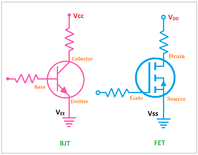
- Vcc and Vee refer to circuits built on bipolar transistors, hence the letters C (collector, collector) and E (emitter, emitter) .
- circuits with Vdd and Vss are built on field-effect transistors, hence D (drain, drain) and S (source, source).
It so happened that npn- and n-channel transistors were more often used, in which a positive voltage must be applied to the collector / drain, and a negative voltage to the emitter / source, so the “polarity” is like that.
For clarity
The designations do not always depend on the actual internal structure and can be “mixed”. In some mikruhs, you can see both types of designation on different legs at the same time. It is often shown that different supply voltages are needed (for example, the Intel 8080 had VCC = +5 V, VDD = +12 V and VEE = -5 V).
Why two letters?
Typically, the voltage on the circuits is indicated by two letters (Uce / Uke – collector-emitter voltage, for example), according to two points between which it is applied.
Abroad, in order to distinguish the supply voltage (Vcc) from the voltage at the output of the transistor (Vc), they write two letters.
Everyone who has dealt with consumer electronics has come across designations such as GND, VEE, VCC on a circuit, connectors or motherboard. What is it and how to use this marking correctly?
What is GND?
GND is the most important designation in the circuit, against which all others are measured. This is the “ground”, zero potential, a common wire for power and signal. In English, ground is earth, hence the abbreviation GND.
Other notations show the potential relative to zero:
- VEE – Voltage Emitter Emitter – minus
- VCC – Voltage Collector Collector – plus.
If field-effect transistors are used in the electronic circuit, then the following markings may occur:
- VDD -Voltage Drain Drain – plus
- VSS – Voltage Source Source – minus.
Despite the name, GND has nothing to do with grounding in electronics, except when shielding is used. It is simply a circuit common to power and an electrical signal against which all other voltage potentials are measured.
Therefore, you can often find other designations on connectors, electronic boards, for example:
Com – Common if the circuit is not actually grounded;
0v.
If mixed analog and digital circuits are used, then separate signal power lines for the analog and digital parts are indicated. In this case, you can find the following notation:
- GNDD, DGND – for digital;
- AGND, GNDA – for analog.
For digital logic systems, ground is the negative power terminal of the chip logic. For analog, this is the battery reference, and the signal is tied to an analog output or input.
Why is it important to determine GND correctly?
When connecting consumer electronics circuits or computers, it is important to correctly determine the zero and carefully follow the GND marking. Modern connectors are usually protected against incorrect inclusion, but even in this case it is useful to make sure that the connection is made correctly. Otherwise, a short circuit will occur and the circuit will fail.
Computers typically use either 5V or 12V power circuits. Although the neutral wire of both circuits is the same color (usually black), each uses a different wire. In typical cases, VCC usually means +5V.
In order not to make a mistake when connecting, you need to find the GND designation on the motherboard and check which wire in the connector goes to this point. Then use the color of this wire if there are no markings on the connectors.
How to balance the number of lines?
In any circuit, all current must return to ground, but each pin has current limits. Therefore, it is reasonable to balance the number of lines for the signal with the number of GND lines for the return current. Ideally, there should be as many common conductors as there are signal conductors, then each of them works like a twisted pair, without affecting the others.
Many thin GND wires are better than one thick one. For digital data, this makes it possible to smooth out the mutual influence of signals and improve the quality of information transmission.
GND on the motherboard circuit in a radio
Many people are interested in what role GND plays on the motherboard or radio circuit and what it is all about. Literally, it is “earth”. Some also use the term in the sense of “mass” or “minus”. In fact, this is a common wire, which is usually white or black. The latter option is more common. However, there are other options for the power cable.
It is important to consider the following decoding when repairing the motherboard:
- We are talking about the point of zero potential of the microcircuit.
- VEE stands for Voltage Emitter Emitter. In this case, we mean minus power in relation to GND.
- VCC stands for Voltage Collector Collector. This is just the plus of power in relation to GND.
Analog ground, in turn, can be abbreviated as AGND or GNDA.
To understand the essence, an elementary example should be given. In the computer case, it was necessary to connect an additional fan so that the unit did not overheat. Standard capacities were not enough. Zero fans, the black wire were connected to the molex connector wire on the power supply. By the way, it is also made in black. In this case, this is the “ground”.
This is important to consider in order calculating the required voltage. Otherwise, a short circuit and subsequent malfunction may occur, which is sometimes impossible to eliminate.
Be sure to pay attention to the sockets with connectors. Sometimes, their design is able to eliminate the wrong connection. By the way, the computer buttons themselves, for example, reboot and turn on, it doesn’t matter at all how to connect, because the main thing here is short circuit. Pros and cons do not play any role here.