Electronic technology is miniaturizing, so microcircuits in TEPBGA packages are becoming more common in electronic equipment, including computers and mobile devices. The article provides an answer to the question “How to solder TEPBGA packages?” in the form of detailed instructions with practical recommendations for soldering at home.
Necessary tools and materials
First, let’s figure out what a TEPBGA package is. The abbreviation TEPBGA stands for “Ball grid array”. In scientific terms, TEPBGA is a package type of surface-mounted integrated circuits. TEPBGA is derived from PGA (“Pin grid array”). TEPBGA pins are solder balls applied to the contact pads on the back of the microcircuit.
The microcircuit is placed on the printed circuit board according to the marking of the first contact on the microcircuit and on the board. The chip is then heated with a soldering station or an infrared source so that the beads begin to melt. Surface tension causes the molten solder to fix the chip exactly above where it should be on the board, and does not allow the balls to deform.
The advantage of the TEPBGA package is its compactness and saving space on the printed circuit board. The conclusions are placed on the lower surface of the element in the form of flat contacts with applied solder in the form of a hemisphere.
In cases of this type, semiconductor microcircuits are performed: processors, FPGAs and memory. The soldering of the element in the TEPBGA package is carried out by heating the element body directly, with the printed circuit board heated using hot air or infrared radiation.
Let’s go directly to soldering the TEPBGA at home.
We will need:
- Solder paste KOKI S3X58-M650-7
- Flux KOKI
- Solder paste spatula (optional)
- Stencil for applying solder paste
- Desoldering Wipes 3S-Wick
- Tweezers
- Insulating tape
Let’s start the soldering process.
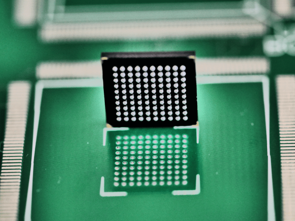
1) The microcircuit before soldering looks like this:
2) To facilitate the process of placing the microcircuit on the board, we will make marks on the board along the edge of the microcircuit body, if there is no silk-screen printing on the board, which shows its position.
Set the temperature to 320–350°C on a hot air gun. For an accurate choice, be guided by the size of the chip package. In order not to damage small parts soldered nearby, we set the minimum speed (pressure) of air.
Hold the hair dryer perpendicular to the board for a minute of warming up. In order not to damage the crystal, we direct the air not to the center, but along the edges, along the perimeter. After a minute, we hook the microcircuit over the edge and lift it above the printed circuit board. If the microcircuit “does not give in”, then the solder has not completely melted; continue heating. Do not use force to lift the chip: there is a risk of damaging the printed circuit board pattern.
3) After the “soldering” process, the printed circuit board and microcircuit look like this:
4) As an experiment, we will apply a flux to the received board and microcircuit.
After warming up, the solder will gather into uneven balls. We apply alcohol rosin (when soldering to the board, it is impossible to use alcohol rosin due to low resistivity), heat it and get:
This is what the board and microcircuit look like after cleaning:
Soldering this chip to the old place just won’t work, which means a replacement is needed.
5) Using a 3S-Wick desoldering braid, clean the boards and microcircuits from the old solder. When cleaning, be careful not to damage the solder mask, otherwise the solder will then spread along the tracks. Result:
6) Let’s start “knurling” new balls. Theoretically, you can use ready-made balls. But it is likely that you will need to decompose more than one or even two hundred of these balls, spending a lot of time and nerves on this. Solder paste stencils can solve this problem.
We recommend KOKI S3X58-M650-7 solder paste for TEPBGA *. We compared our solder paste and a cheap analogue offered by another company, which we will not name for reasons of corporate ethics. The photo shows the result of heating a small amount of paste. KOKI paste immediately turns into a shiny smooth ball, and cheap ones will break up into many small balls.
*When rolling solder paste balls, pay attention to the chip body: if it is not marked “Pb free”, use lead-containing paste SS48-A230 . This is due to the lower melting point of lead-containing paste. We set the hair dryer at 250–270 ° C.
So, we fix the microcircuit in a stencil for applying solder paste using mounting tape:
Then, with a spatula or just a finger, apply solder paste.
After applying, hold the stencil with tweezers and melt the paste. The temperature on the hair dryer is set to no more than 300 ° C. We hold the hair dryer perpendicular to the board. We hold the stencil with tweezers until the solder solidifies completely, because when heated, the stencil bends.
After the flux has cooled, remove the fixing tape and use a hair dryer with a temperature of 150 ° C to gently heat the stencil until the flux melts. After that, carefully separate the chip from the stencil. As a result, we get smooth balls. The microcircuit is ready to be placed on the board:
7) We start soldering the microcircuit to the board.
At the beginning of the article, we advised you to make risks on the board. If you nevertheless ignored this advice, then we do the positioning as follows: turn the microcircuit over with the pins up, apply the edge to the nickels so that they coincide with the balls, mark where the edges of the microcircuit should be (you can slightly scratch it with a needle).
First one side, then perpendicular. Two risks are enough. Then we put the risk chip on the board and try to catch nickels at the maximum height by touch with balls. The balls should stand on the remnants of the old balls on the board.
You can install it by simply looking under the case, or by silk-screen printing on the board.
We warm up the chip again until the solder melts. The microcircuit itself will precisely fall into place under the action of the surface tension forces of the molten solder. Important: we apply a small amount of flux! We again set the temperature of the hair dryer to 320–350 ° C, depending on the size of the microcircuit case. For lead-containing microcircuits, we set 250–270 ° C.