· Editor · 14 min read
FR4 Material: Properties, Uses, and Design Considerations
FR4 material is the backbone of modern circuit board production. It shows up in smartphones, industrial controllers, automotive dashboards, and countless other devices. But not all FR4 is th
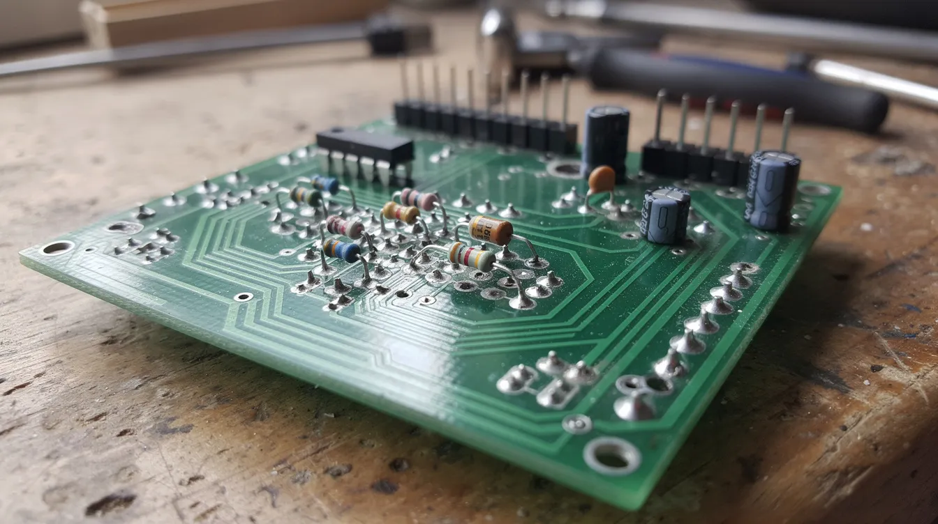
FR4 material is the backbone of modern circuit board production. It shows up in smartphones, industrial controllers, automotive dashboards, and countless other devices. But not all FR4 is the same. Understanding its properties helps you pick the right grade for your next design.
Key Takeaways
FR4 is a glass reinforced epoxy laminate. It serves as the standard base material for most printed circuit board designs.
FR4 combines flame retardant performance, strong electrical insulation, and solid mechanical strength at low cost.
The typical dielectric constant range falls between about 3.8 and 4.8 at 1 MHz. Standard glass transition temperature sits around 130–140 °C, while high-Tg grades reach 150–180 °C.
FR4 works well for general-purpose and consumer electronics. High frequency circuits often need better laminate materials.
Correct FR4 grade, board thickness, and Tg selection are vital for long-term reliability and signal integrity.
What Is FR4 Material?
FR4 material is a flame retardant glass epoxy laminate. It is the most widely used substrate material for printed circuit boards. Engineers and fabricators rely on it as the default PCB material across dozens of industries.
FR stands for “flame retardant.” The “4” is a NEMA designation for this specific glass-reinforced epoxy resin system. So when someone says “FR 4,” they mean this exact composite class.
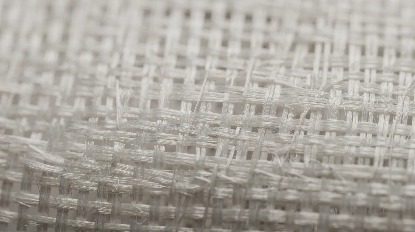
The structure is straightforward. Manufacturers weave fiberglass into woven cloth. They soak it with epoxy resin. Then they cure it under heat and pressure into rigid sheets. After curing, copper foil bonds to one or both sides.
FR4 acts as the insulating core in almost every standard rigid circuit board. You find it in consumer electronics, telecom gear, and industrial systems. Its key traits include electrical insulation, mechanical strength, moderate thermal stability, and compliance with the UL94 V-0 flammability class.
Chemical Composition and Structure
FR4 is a composite, not a single pure material. It has two main parts plus additives. Exact performance varies among manufacturers and resin systems.
Here are the main constituents:
Fiberglass reinforcement: E-glass fibers woven into cloth provide stiffness and tensile strength. The weave style and glass-to-resin ratio affect the material’s dielectric constant, warpage, and mechanical properties.
Epoxy resin matrix: This thermoset polymer locks fibers in place. It provides electrical insulation and delivers flame retardant behavior. Once cured, it cannot be re-melted.
Flame retardant additives: Traditional FR4 uses brominated flame retardant epoxy resin. Newer versions use phosphorus or other systems for low-halogen or halogen-free compliance under RoHS and REACH rules.
Fillers and catalysts: Small amounts of other additives tune cure speed, resin content, and moisture resistance.
Because FR4 is a composite, two boards labeled “FR4” from different suppliers may differ in dielectric constant, loss tangent, or Tg. Always check the manufacturer’s datasheet before committing.
Key Material Properties of FR4
FR4 earns its place in the electronics industry through a strong balance of mechanical, electrical, and thermal properties. Here is a quick overview of each group.
Mechanical performance stands out. FR4 has high mechanical strength due to woven glass fibers. Typical flexural strength lands around 350–420 MPa. FR4 panels resist mechanical stress and deformation. The material maintains structural integrity during drilling and milling operations. It also exhibits a high strength-to-weight ratio in PCB applications.
Electrical insulation is excellent. FR4 has excellent electrical insulation properties and high dielectric breakdown strength. Dielectric strength runs about 20–40 kV/mm. Volume resistivity stays above 10⁸ ohm-cm under dry conditions. These values protect against shorts between copper layers.
Moisture absorption is low. FR4 exhibits low moisture absorption of 0.10% after 24 hours in water. This supports use in humid conditions with limited swelling. Still, prolonged exposure can degrade electrical performance over time.
This combination of properties makes FR4 a reliable dielectric material for multilayer PCBs in many industries.
Electrical Properties and Dielectric Constant
Electrical properties drive signal integrity and high frequency circuit performance. Getting them right matters for every PCB design.
Dielectric constant (Dk) describes how much the material slows an electrical signal. FR4 has a dielectric constant of 4.2 to 4.8 at 1 MHz. The broader FR4 dielectric constant range spans about 3.8 to 4.8 depending on resin content and weave style. The material’s dielectric constant affects signal transmission speed in PCBs. Lower Dk means faster propagation.
As frequency rises, Dk decreases. For example, FR4 may show εr of about 4.3 at 100 MHz but drop to 3.9–4.1 in the GHz range. Designers must account for this shift in impedance control and propagation-delay calculations.
Dissipation factor (Df), also called loss tangent, measures energy lost as heat. FR4 has a dissipation factor of around 0.020. The full range for standard FR4 runs from 0.015 to 0.025 depending on grade and frequency. Higher Df means more signal loss per unit length.
Dk variation across the panel and between lots can reach several percent. FR4’s dielectric constant varies up to 10% at high frequencies. These swings complicate strict impedance matching. Dielectric constant variations in FR4 can lead to signal degradation. For this reason, FR4 is not suitable for controlled impedance boards in demanding high speed designs.
Thermal Properties and Glass Transition Temperature
FR4 performance changes near its glass transition temperature. Tg is the single most important thermal spec on any FR4 datasheet.
Standard FR4 has a glass transition temperature around 130 °C to 140 °C. Higher Tg variants can handle temperatures of 170 °C to 180 °C. These high-Tg grades suit lead-free soldering, automotive under-hood zones, and power electronics.
Above Tg, the epoxy resin softens. The coefficient of thermal expansion in the Z-axis rises sharply. Repeated cycles above Tg can crack via barrels and cause delamination. This thermal expansion is the leading cause of via reliability failures in multilayer PCBs.
Related thermal parameters appear on datasheets too:
Decomposition temperature (Td): The point where resin breaks down. Typical values range from 300–360 °C.
Thermal conductivity: FR4 has a low thermal conductivity of about 0.3 W/m·K. Heat spreads poorly through the laminate.
Because of this low thermal conductivity, FR4 materials may require additional thermal management for high-power components. Metal core PCBs or embedded copper planes can help spread heat in dense designs. Standard FR4 can withstand normal soldering temperatures without issue.
Flame Retardant Behavior and Safety
Flame retardant performance is central to why the PCB industry uses FR4 as the default base material. FR4 is widely used in electronics for its flame-retardant properties.
FR4 meets the UL94 V-0 flammability standard. This means samples stop burning within 10 seconds. No flaming drips fall from the material. FR4 self-extinguishes when ignited, preventing fire spread within equipment.
The flame retardant additives inside the epoxy resin slow combustion. They form a protective char layer when exposed to heat. This char blocks oxygen and limits further damage. The flame retardance of FR4 improves fire safety in consumer electronics, household appliances, telecom systems, and industrial control gear.
Modern regulations push manufacturers to reduce certain brominated flame retardants. This drives development of halogen-free FR4 families. These newer systems meet the same UL94 V-0 rating but use phosphorus-based chemistry instead.
FR4 as a PCB Base Material
FR4 serves as the standard base material for rigid printed circuit boards. Its role in PCB manufacturing is hard to overstate. FR4 is cost-effective compared to specialized high frequency materials. This cost effectiveness explains its dominance.
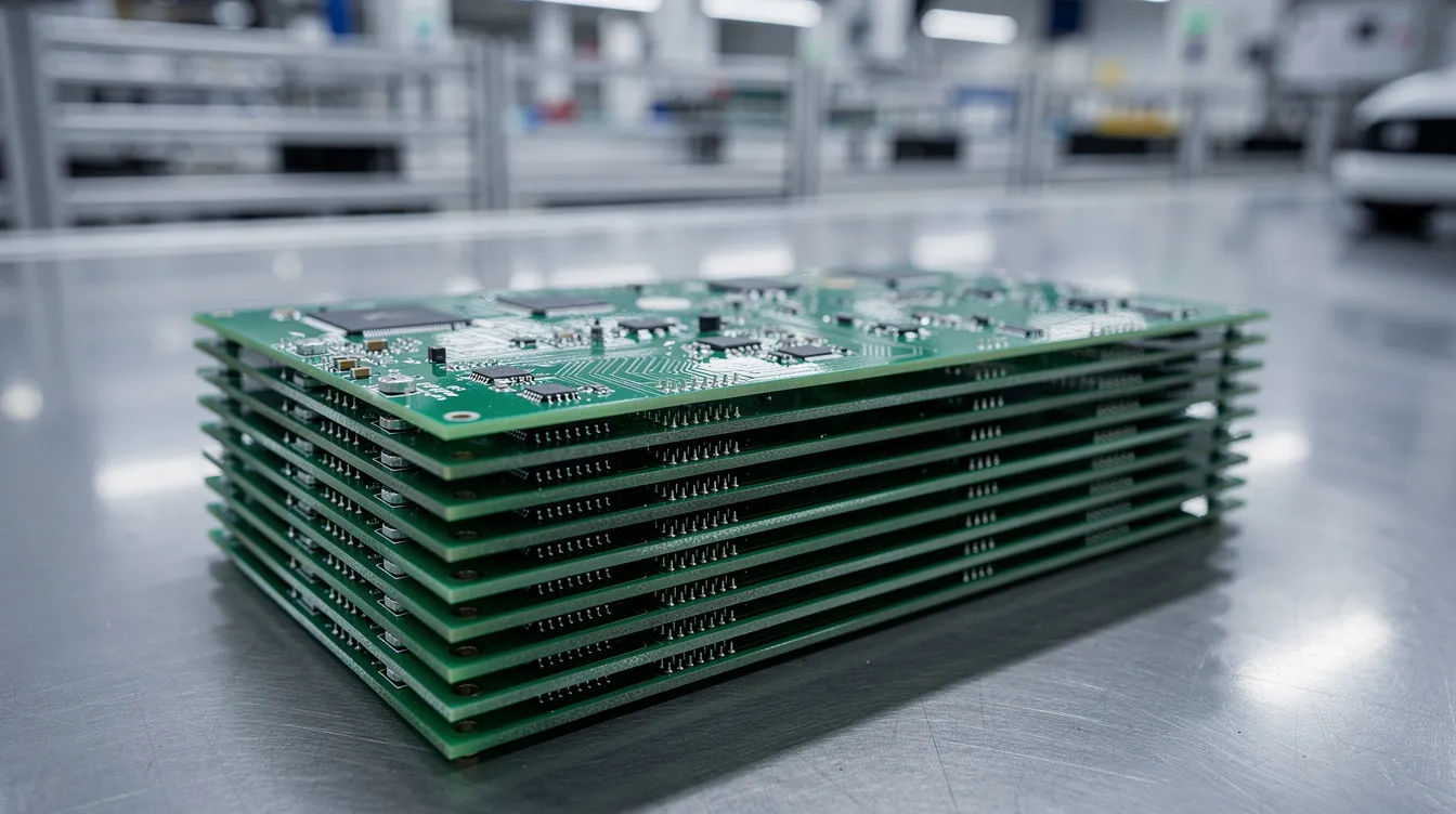
Manufacturers laminate copper foil to FR4 sheets. This creates single-sided, double-sided, or multilayer circuit board structures. Prepreg layers bond additional copper layers in multilayer designs. The FR4 core provides electrical insulation between copper layers. It maintains layer spacing and resists mechanical stress during assembly.
FR4 thickness ranges from 0.2 mm to 3 mm. Standard FR4 thickness is 1.57 mm (about 0.062 inches). Common options include 0.8 mm, 1.0 mm, 1.6 mm, and thicker cores. Designers choose board thickness based on stiffness needs and impedance targets.
FR4 is primarily used in mass-production PCB applications because of its low cost. Its compatibility with standard drilling, plating, and solder mask processes keeps PCB fabrication simple. However, FR4 cannot bend and is not suitable for flexible applications. Flex circuits need polyimide or similar substrates.
Thickness, Density, and Mechanical Design
FR4 thickness, density, and mechanical rigidity shape a board’s functionality in the final product. These factors also affect cost and weight.
The density of FR4 is between 1.8 and 2.0 g/cm³. Variation depends on resin content, glass style, and core thickness. A typical manufacturer spec sheet lists specific gravity around 1.85.
Thicker boards improve rigidity. A 3.2 mm board resists warpage far better than a 0.8 mm board. Thicker FR4 boards support more complex multilayer designs with more copper layers. But weight and material cost increase with thickness.
Thinner boards suit compact devices. Thinner FR4 boards are preferred for compact devices like wearables, Bluetooth accessories, and USB connectors. But they are fragile. They can warp during reflow if unsupported.
FR4 thickness affects impedance matching in high frequency designs. Dielectric spacing between layers sets characteristic impedance for high speed traces. So thickness is not just a mechanical choice. It is an important factor in electrical performance too.
High Frequency and High-Speed Design Limits
FR4 works well up to moderate speeds. But it runs into limits at high frequency.
At RF and microwave circuits frequencies, FR4’s higher dissipation factor creates noticeable signal loss over long traces. FR4 has high signal loss in high-frequency applications. FR4 has relatively high dielectric losses which complicates high-frequency applications. As frequency increases, signal loss increases too.
FR4’s dielectric constant can shift at higher frequencies. FR4 is not ideal for high-frequency applications due to dielectric instability. This undermines tight impedance control in high frequency circuits.
Designers often cite about 0.5 GHz as the upper safe band for standard FR4. For multi-gigabit digital links or GHz-range RF front-ends, most high frequency laminates offer better results. High frequency materials like Isola FR408 show Dk around 3.65 and Df about 0.0125 at 10 GHz. These values beat standard FR4 by a wide margin.
Hybrid stackups offer a middle ground. Some designers combine FR4 with specialized laminates in critical RF zones. FR4 handles power and low-speed digital layers. High frequency laminates handle the sensitive signal paths. This approach balances cost and thermal performance.
Typical Applications of FR4 Material
FR4 is the workhorse material across the electronics industry. Here are the main application areas:
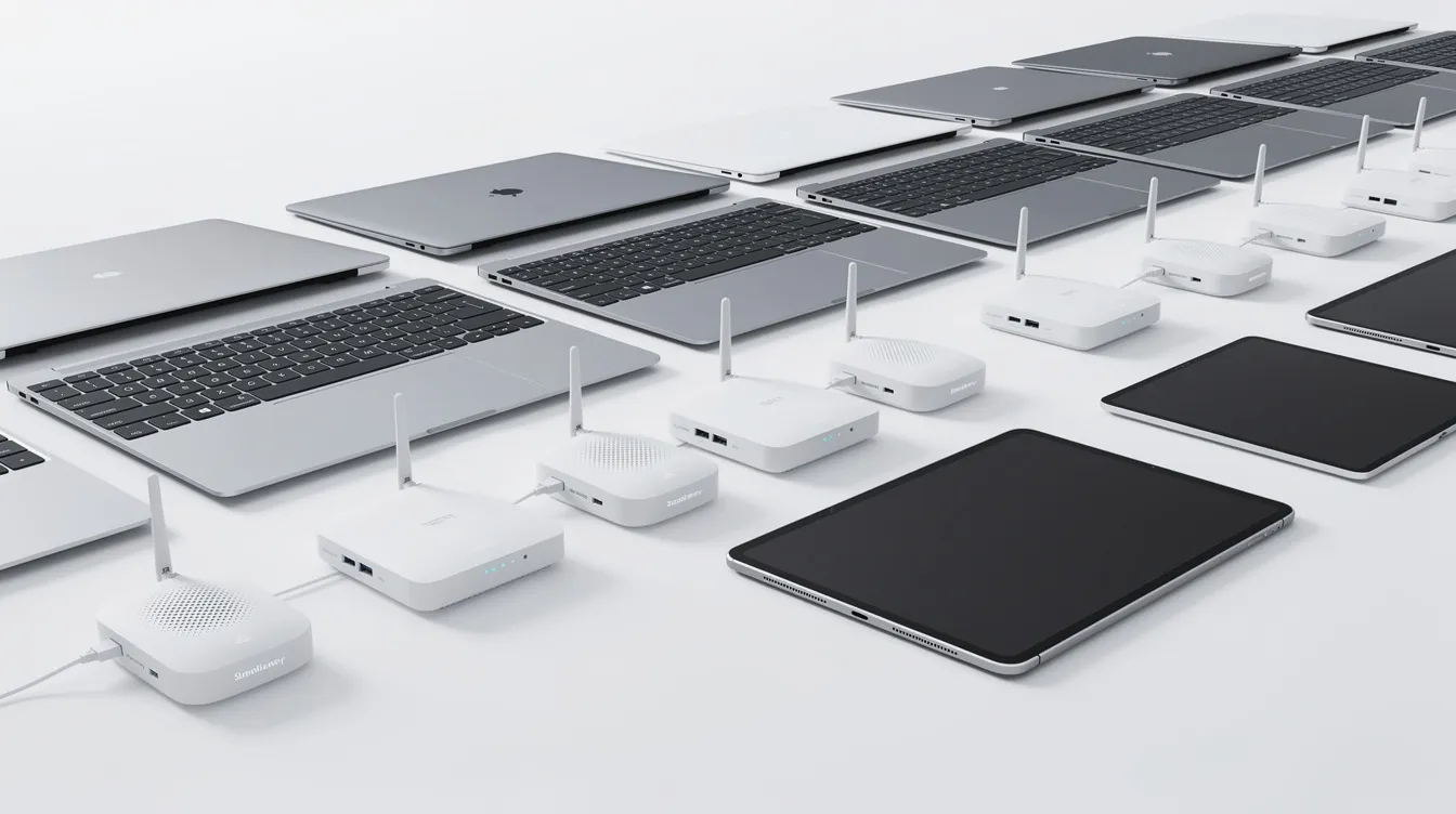
Consumer electronics: Smartphones, laptops, TVs, set-top boxes, game consoles, and home routers use standard FR4 boards. These devices need low cost and reliable electrical insulation. Standard Tg grades handle the modest thermal loads.
Industrial and automation: PLCs, motor drives, power supplies, and sensor interface boards benefit from FR4’s mechanical strength and insulation. Mid-Tg or high-Tg grades suit higher ambient temperatures in these electronic applications.
Automotive interior electronics: Infotainment systems, dashboard controllers, and LED drivers work on FR4 if temperatures stay within Tg limits. Under-hood locations need high-Tg grades or alternative PCB substrates.
Non-copper laminate uses: FR4 sheet stock without copper serves as structural insulation plates, mounting panels, and transformer barriers. Its mechanical rigidity and flame retardance make it useful beyond circuit boards.
Selecting the Right FR4 Grade and Specifications
Material selection is a trade-off between cost, thermal rating, and electrical performance. Getting it wrong can cause field failures.
Here is a practical checklist:
Choose Tg based on thermal exposure. Lead-free reflow peaks at 245–260 °C. Standard FR4 may survive one cycle. Multiple reflow passes or high ambient temperatures demand high-Tg grades. Heat resistance matters for long-term reliability.
Match Dk and Df to signal speed. For high speed digital or high frequency designs, check the dissipation factor and dielectric constant at your target frequency. Even small Df reductions save signal integrity over long traces.
Review IPC-4101 slash sheets. These define material classes, Tg ranges, weave styles, and performance tiers. Cross-reference them with the manufacturer’s datasheet for Dk, Df, Td, and CTE values.
Verify certifications. Confirm UL94 V-0 flame retardant rating, RoHS compliance, and any application-specific requirements. Documentation matters for end-product approvals.
Talk to your fabricator early. Some FR4 grades cost more or have longer lead times. What your fabricator stocks affects your choices. Stocking levels for specialized laminates vary by region.
Proper storage and baking can mitigate moisture absorption issues in FR4 materials. This step is critical before assembly in humid conditions.
Standards, Compliance, and Environmental Aspects
FR4 laminate materials must meet electrical, flammability, and environmental standards. These requirements shape what you can use in your product.
| Standard | What It Covers |
|---|---|
| UL94 V-0 | Flammability rating for plastic materials |
| IPC-4101 | Base material qualification and performance classes |
| IPC-A-600 | Acceptance criteria for board quality and defects |
| IPC-6012 | Fabrication quality for rigid boards |
| RoHS / REACH | Restrictions on hazardous substances |
| IPC-4101 slash sheets define Tg, Td, electrical strength, and weave options for each material class. IPC-A-600 and IPC-6012 set acceptance criteria for weave exposure, bonding quality, and surface defects. |
RoHS and REACH rules limit certain hazardous substances. These rules push adoption of low-halogen or halogen-free FR4 variants. Designers may need full documentation on FR4 composition, flammability class, and environmental profile for end-product approvals.
Future Trends in FR4 and PCB Base Materials
FR4 formulations keep evolving. The push comes from higher data rates and stricter environmental codes.
Low-loss FR4-like grades: Newer formulations reduce dissipation factor while staying cost-competitive with classic FR4. Designers want Df around 0.01 or lower at several GHz for 25–56 Gbps links.
Halogen-free and low-smoke variants: Stricter safety codes drive these options. The trade-offs in cost and performance are shrinking each year.
Hybrid stackups: Advanced multilayer PCBs mix FR4 with high frequency laminates or metal core PCBs. This approach balances thermal and electrical demands without the full cost of exotic substrates.
Better characterization data: Manufacturers now provide Dk and Df curves across wider frequency and temperature ranges. This helps designers model signal integrity more accurately.
FR4 will remain dominant for standard boards. But high speed and RF designs will continue to lean on specialized laminates and high frequency materials.
FAQ
This section answers common practical questions about FR4 material.
Is FR4 material safe to use in household consumer electronics?
Yes. FR4 with a UL94 V-0 flame retardant rating is accepted for TVs, laptops, routers, and kitchen appliances. Modern FR4 laminates often comply with RoHS and similar regulations. These rules limit hazardous flame retardant additives.
Designers still need proper enclosure design and fusing. FR4 improves safety but does not eliminate all fire risk on its own.
Can I use standard FR4 for high frequency RF circuits?
Short RF paths at lower GHz ranges can sometimes run on FR4. But signal loss and Dk variation limit performance. For antennas, microwave circuits, or long RF lines, low-loss high frequency laminates give better results.
Simulate both loss and impedance tolerance before choosing FR4 for any high frequency circuit. Check the dissipation factor at your target frequency.
What is the difference between FR4 and G-10 material?
Both are glass epoxy laminates. FR4 includes flame retardant chemistry. Classic G-10 does not. FR4 replaces G-10 in most applications where flame retardant performance is required by safety standards.
Many suppliers no longer stock G-10 for electronics. FR4 offers similar structural integrity plus improved fire behavior.
How does moisture affect FR4 electrical insulation over time?
FR4 exhibits low moisture absorption, less than 0.1%. But absorbed moisture can raise the dielectric constant and loss. This matters in sensitive high frequency circuits and in humid conditions.
Use conformal coating, controlled storage, and baking before assembly when boards face outdoor or humid environments. A solder mask layer also helps protect exposed surfaces from water absorption.
When should I move from standard FR4 to high-Tg or alternative laminates?
High-Tg FR4 suits lead-free solder profiles, power electronics, and automotive zones with sustained high temperatures. Standard Tg (130–140 °C) works for most consumer electronics with moderate thermal loads.
Designs above a certain data rate or RF frequency need low-loss laminates instead of standard FR4. Review maximum operating temperature, solder profile, and signal bandwidth together. Then lock in your base material choice.