· Editor · 15 min read
Open Circuit vs Closed Circuit: What's the Difference and Why It Matters
An open circuit has a break, so current cannot flow. A closed circuit is a complete loop, so the load operates. This guide covers both states, with examples and how to test them.
Understanding the difference between an open circuit and a closed circuit is one of the most important skills in electrical work. Whether you wire a home outlet or debug a faulty gadget, this concept sits at the center of everything. This guide breaks down both states with clear examples, formulas, and practical advice.
Open Circuit vs Closed Circuit: The Short Answer
An open circuit has a break in its path. Electric current cannot flow, so devices stay off. A closed circuit is a complete loop. Current flows through the load, and devices operate.
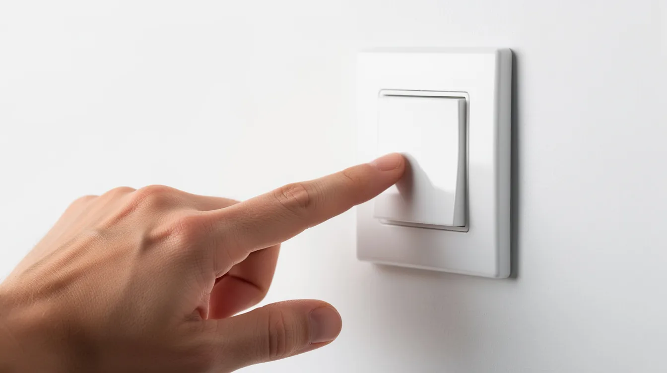
Think about a light switch in your home. When the light switch is in the closed position (ON), the circuit is complete. The light bulb glows. Flip the switch OFF, and you create an open circuit. The lamp goes dark.
This open vs closed idea works the same way in DC circuits (like a car battery powering headlights) and AC circuits (like your home mains powering a kitchen light). Both require a complete loop for current to flow.
How We Compare Open and Closed Circuits
This comparison matters for students, technicians, and anyone who works with electrical equipment. Knowing the key differences helps you diagnose faults faster and design safer systems.
This article compares open and closed circuits using clear, practical criteria:
Path continuity - is the loop complete or broken?
Current flow and resistance behavior
Voltage distribution in the circuit
Power transfer and device operation
Typical real-world causes and examples
Safety and troubleshooting impact
Each circuit state gets its own breakdown with formulas, real examples, and field-testing tips.
Three Core Circuit States You Must Know
There are three basic states in simple electrical circuits. This article focuses on the open circuit vs closed circuit comparison. But a short circuit deserves a brief mention for context.
Think of these as three “modes” a circuit can be in. Knowing which one you see on a meter helps you act fast.
1. Closed Circuit (Normal Operating State)
A closed circuit is a complete path from the power source, through the load, and back to the source. A closed circuit represents the ON state of a switch. A closed circuit allows electrical current to flow continuously.
Picture a 9 V battery connected to an LED through a closed switch. The loop is complete. The LED lights up.
Here is what a multimeter reads in this state:
Continuity test: low resistance or a beep between key points.
Voltage: the supply voltage appears across the load, not across the closed switch.
Current: a non-zero value that follows Ohm’s Law (I = V / R).
This is the desired state for proper operation at home, in cars, and in industry.
2. Open Circuit (Broken or Switched-Off State)
An open circuit occurs whenever there is a break in the conductive path. Current drops to zero. An open circuit represents the OFF state of a switch. Open circuits prevent current flow due to a break in the path.
Consider a 120 V home circuit. The light switch is OFF. The lamp does not glow.
Here is what happens inside the circuit:
Resistance between the open points becomes very high. It approaches infinite resistance.
No current flows through the load. The load receives no power.
The source voltage appears almost fully across the open gap.
An open circuit can be intentional (a switch or relay) or accidental (a broken wire or blown fuse).
3. Short Circuit (For Contrast Only)
A short circuit is not the same as a closed circuit. It is a different fault state.
A short circuit creates a low resistance path that bypasses the intended load. Current spikes to dangerous levels.
Here is a quick contrast:
Short: the path has near zero resistance. Current is dangerously high.
Open: the path is broken. Resistance is very high. Current is zero.
Closed and healthy: resistance equals the designed load. Current stays in the normal range.
The rest of this article focuses on open vs closed behavior.
Closed Circuit in Detail
A closed circuit is the “ON and working” state for any system. Below, we break down its structure, behavior, and real examples.
Structure and Requirements of a Closed Circuit
A simple closed circuit needs four elements:
Energy source - a battery, power supply, or mains transformer.
Conductors - wiring or PCB traces that form the current path.
Load - a light bulb, motor, heater, or electronic device.
Control and protection - a switch, fuse, or circuit breaker.
Electricity requires a continuous loop to circulate. All elements must connect in a closed loop back to the source. Even complex circuits with parallel circuits and multiple branches reduce to many closed loops. Each loop obeys the same rule.
Electrical Behavior in a Closed Circuit
Let’s use a concrete example. A 12 V car battery feeds a 6 Ω headlamp.
Using Ohm’s Law: I = V / R = 12 V / 6 Ω = 2 A.
Voltage distribution:
Most of the supply voltage appears across the load.
Good wires and a closed switch have a very small voltage drop. With 0.2 Ω of wire resistance, the drop is about 0.4 V.
Power transfer:
- P = V × I. For this lamp, power is about 24 W.
Closed circuits maintain a voltage difference across components. In a healthy closed circuit, current, voltage, and power all match the design values.
Real-World Examples of Closed Circuits
Here are four common examples of a complete circuit in action:
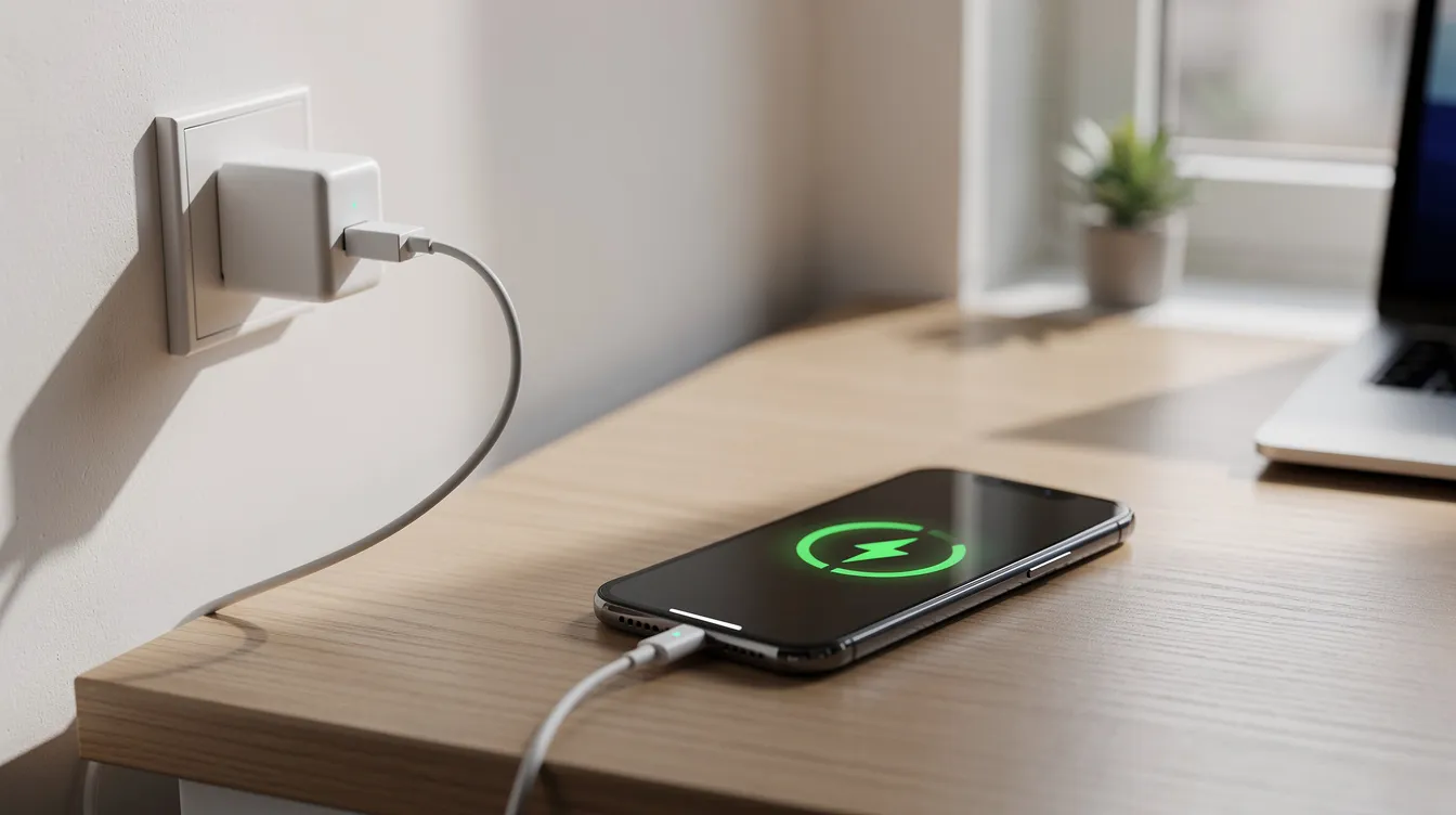
Phone charging: Your smartphone charges when the USB cable and adapter seat well. The closed path runs from the power supply through the cable to the battery’s positive terminal, through the battery to the negative terminal, and back.
Home Wi-Fi router: The router stays powered as long as its plug, socket, and internal power path form a closed loop. The load is the router’s electronics.
Industrial conveyor belt: The motor runs while all safety guards and emergency stops remain engaged. Control panels keep the circuit in a closed state.
LED strip lighting: A kitchen under-cabinet LED strip glows when the wall dimmer is ON. The dimmer completes the closed path from the power source to the strip and back.
Open Circuit in Detail
An open circuit is the “OFF, broken, or interrupted” state. This state can be safe and deliberate. It can also be a hidden fault.
What Makes a Circuit Open?
The loop can break at several places:
An open switch or relay contact.
A disconnected terminal at the source or load. A loose terminal is a frequent culprit.
A broken wire in a cable or PCB trace. A broken wire is a common cause of open circuits.
A faulty component that has failed open. Burnt-out components like fuses create open circuits.
Loose connections often cause an intermittent open circuit. The circuit works sometimes and fails at other times. Corroded terminals can also lead to open circuit conditions over time.
A single break anywhere in a series current path opens the entire loop. But in parallel circuits, one branch can be open while other parallel paths still carry current.
Electrical Behavior in an Open Circuit
Current behavior:
An open circuit prevents electrical current from flowing. The electric circuit has zero current flow because the loop is not complete.
Voltage behavior:
Voltage remains present across an open circuit’s break. In a home lamp circuit, full mains voltage appears across the open switch when it is OFF. With a battery and an open wire, full battery voltage appears between the open conductor ends.
You can measure voltage across the two terminals of the gap. But nothing works. No current means no power reaches the load.
Resistance:
Open circuits have infinite resistance at the break point. A multimeter in resistance mode shows “OL” (over limit) or mega-ohms between the broken ends. You cannot measure current because there is none.
This is why you can measure voltage in an open circuit even though no device operates.
Intentional vs Accidental Open Circuits
The physics is the same in both cases. But intent and safety outcome differ.
Intentional open circuits:
Light switches in homes disconnect the phase conductor.
Emergency stop buttons in factories open control circuits.
Disconnect switches in solar PV arrays create open circuits during maintenance.
Safety devices intentionally create open circuits to prevent hazards.
Accidental open circuits:
A cracked solder joint on a smartphone charging port.
A corroded car battery terminal that stops starter motor current.
A broken flex cable in a laptop hinge that kills the display backlight.
Open circuits can result from broken wires or faulty switches without warning.
Visual inspection can reveal signs of open circuit issues. Look for burn marks, corrosion, or loose connections. Use a multimeter to check for continuity in suspected open circuits.

Open vs Closed Circuit: Side-by-Side Comparison
Here is a fast way to scan the key differences between these two circuit states.
| Dimension | Closed Circuit | Open Circuit |
|---|---|---|
| Path continuity | Complete path, closed loop | Broken path, open loop |
| Current | Normal current flow per design | Zero current flow |
| Voltage distribution | Voltage drop appears across the load | Full voltage appears across the open gap |
| Resistance | Finite design value (load resistance) | Very high, approaches infinite resistance |
| Device state | Operating, doing work | Off or faulted |
| Typical cause | Normal operation, switch ON | Switch OFF, broken wire, component failure |
| Safety aspect | Normal operation, protective devices active | Safe isolation in many cases, but voltage potential still present |
The core difference: a closed circuit has a complete path for electrical energy to flow. An open circuit has a break that stops everything.
Where Each Circuit State Is “Best” or Most Useful
Open vs closed is not about good vs bad. These are different tools. Engineers choose when a circuit should be open or closed under normal conditions.
Closed Circuits: Best for Delivering Power and Doing Work
Closed circuits are essential whenever electrical energy must flow to a load.
HVAC systems in office buildings need closed power loops to run compressors and fans.
Data centers require stable, closed paths to keep servers running around the clock.
Electric vehicles from recent models depend on closed traction motor circuits for propulsion.
Designers focus on low resistance connections and robust terminations. These keep the conductive path closed and reliable. Even a loose connection can open the circuit and shut down critical equipment.
Open Circuits: Best for Control, Isolation, and Safety
Open circuits are valuable when you need something to stop, isolate, or stay off. Intentional disconnections are used in safety devices to create open circuits.
Household switches disconnect lighting circuits at night.
Interlock switches on microwave oven doors open the circuit when the door opens. This prevents electric shock.
Lock-out/tag-out systems hold high-voltage feeds in an open state during maintenance work.
Many safety standards (like IEC and NFPA 70E) rely on open-circuit logic for fail-safe design. If a wire breaks, the circuit opens and the machine stops. That is safer than a machine that keeps running after a fault.
Quick Comparison: How to Identify Open vs Closed in the Field
This is a fast reference for technicians and learners. Use both visual cues and meter readings before deciding.
Closed circuit - best identified by a working load (lamp on, motor spinning) and measurable current.
Open circuit - best identified by a non-working load, full voltage across the switch or gap, and zero current.
Closed circuit - continuity tests show low resistance or a beeping path in continuity mode.
Open circuit - continuity tests show “OL” or mega-ohms between the open points.
Closed circuit - in voltage mode, the voltage drop appears across the load, not across the switch.
Open circuit - in voltage mode, full supply voltage appears across the open component.
Always verify with a meter. A device that looks “off” could have a closed circuit with a burned-out load. A device that looks “fine” could have an internal open.
How to Decide If a Circuit Should Be Open or Closed
This section is a simple decision guide for design, wiring, and troubleshooting. The factors below shape whether you want a normally open or normally closed path.
Choose Based on Safety Requirements
Fail-safe design means the system goes to a safe state when something breaks.
When a normally closed path is safer:
Emergency stop circuits open when a wire breaks. Loss of continuity stops the machine.
Guard door switches use this logic. If the guard opens, the circuit opens.
When a normally open path works fine:
Non-critical lighting and small appliances in homes use normally open switches.
Doorbell pushbuttons stay open until pressed.
Choose Based on Control Logic and User Experience
User expectations shape whether circuits spend most of their time open or closed.
A doorbell pushbutton stays open until you press it. Then it closes for a moment.
A thermostat contact closes only when heating or cooling is needed.
Control panels often mix both states. Different signals use different “normal” positions.
The design must match what the user expects. A light switch that stays on when you flip it “OFF” is a dangerous fault, not a feature.
Choose Based on Maintenance and Energy Use
Leaving circuits closed all the time uses electrical energy. It can also age electrical components faster.
Keep standby loads in an open state until needed. This cuts idle power draw.
Use open-circuit isolation for rarely used branches. This simplifies maintenance.
During installation of long cable runs, open-circuit testing (insulation and continuity tests) is standard practice.
Engineers balance uptime needs against energy cost and component life. The right mix depends on the system.
Which Circuit State Do You Need Right Now?
Here is a quick decision guide for three common scenarios:
System design: Choose a closed circuit state when the device must run and deliver power to a load. Choose an open circuit state when you need safe isolation for service or shutdown.
Troubleshooting: Suspect accidental open circuits when a device is off, voltage is present, but current and continuity are not. Check for blown fuses, broken connections, and faulty switches.
Daily operation: Use switches and protective devices to move between open and closed states as needed. Never bypass a safety device to force a circuit closed.
Ask yourself one question: “Is my problem that the circuit should be closed but is open, or the other way around?”
That question solves most electrical faults.
Final Thoughts
A closed circuit means a complete path. Current flows. Work gets done. An open circuit means a broken path. No current flows. The system is off or isolated.
Almost every electrical problem boils down to knowing whether the path should be open or closed at that moment. Master this concept, and you hold the key to troubleshooting any electrical system.
Remember: complete loop means power. Broken loop means none.
FAQs About Open vs Closed Circuits
This FAQ clears up common points of confusion from beginners and new technicians.
What is the main difference between an open circuit and a closed circuit?
The main difference is path continuity. A closed circuit has a complete path, so current flows. An open circuit has a break, so current stops.
Voltage may exist in both states. But only a closed circuit delivers power to loads. The key characteristics to check are continuity and current flow.
Why can I measure full voltage in an open circuit even though nothing works?
Think of water pressure behind a closed valve. The pressure is there, but no water moves. Voltage works the same way. The voltage potential from the power source pushes against the gap.
No current means no voltage drop across the load. So the meter sees full source voltage across the open break. Voltage remains present across open circuit points despite no current flow.
Does the open vs closed concept apply the same way in AC and DC circuits?
Yes. Both AC and DC need a complete loop for current to flow. Frequency and waveform do not change the need for a closed path.
AC example: a home outlet powers a lamp through a light switch. Switch OFF = open circuit. Switch ON = closed circuit.
DC example: a battery-powered toy needs a direct connection from the positive terminal through the motor to the negative terminal and back. Remove one battery contact, and the circuit is open.
How can I quickly test if a circuit is open or closed?
Safety first: de-energize the circuit before running continuity tests.
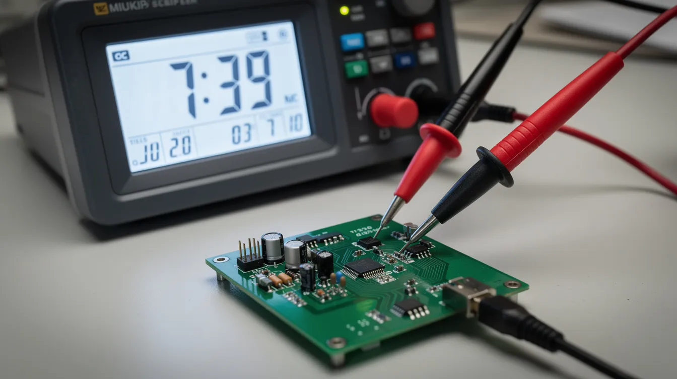
For a de-energized circuit, set your multimeter to continuity mode or resistance mode. Touch the probes to the two terminals of the path you want to test.
Low resistance or beep = closed, complete path.
“OL” or very high reading = open, broken path.
For live circuits (only when trained and safe), you can measure current. Zero current in a path that should conduct electricity signals an open. You can also measure resistance across individual components to find a faulty component.
Are open circuits always safe to touch?
No. An open circuit can still sit at dangerous voltage. Open circuits do not pose immediate fire risks like short circuits. But exposed conductors can deliver a lethal electric shock.
Treat all exposed conductors as live until you verify they are de-energized. Follow local electrical codes. Use proper personal protective equipment. Electrical safety depends on verification, not assumptions.
Can a device fail “open” inside even if the wiring looks fine?
Yes. Internal electrical components like fuses, PCB traces, relay coils, and LEDs can fail open. A cracked solder joint inside a circuit board creates an open without visible external damage.
This is why visual inspection alone is not enough. Use targeted continuity tests across suspected components. Set the multimeter to measure resistance across each part. An “OL” reading on a part that should conduct tells you the circuit is open inside that component.
Redundant paths in a design can keep a system running even when one internal path fails open. But single-path circuits stop working entirely.